
Page 168 - Demo
P. 168
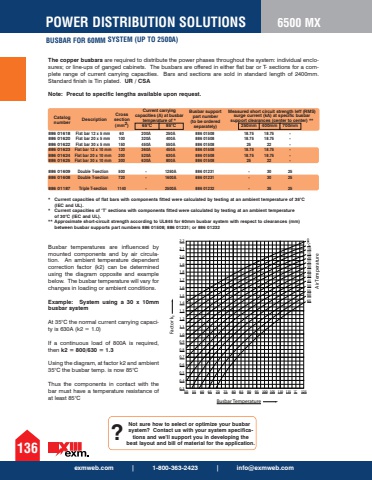
exmweb.com | 1-800-363-2423 | [email protected] DISTRIBUTION SOLUTIONSBUSBAR FOR 60MM SYSTEM (UP TO 2500A)136886 01618 886 01620 886 01622 886 01623 886 01624 886 01625 886 01609 886 01608 886 01187Flat bar 12 x 5 mm Flat bar 20 x 5 mm Flat bar 30 x 5 mm Flat bar 12 x 10 mm Flat bar 20 x 10 mm Flat bar 30 x 10 mm Double T-section Double T-section Triple T-section 60 100 150 120 200 300 500 720 1140 200A 320A 450A 360A 520A 630A - - -250A 400A 550A 450A 630A 800A 1250A 1600A 2500A 886 01508 886 01508 886 01508 886 01508 886 01508 886 01508 886 01231 886 01231 886 01232 18.75 18.75 25 18.75 18.75 25 - - -18.75 18.75 22 18.75 18.75 22 30 30 35- - - - - - 25 25 25Catalog number DescriptionCross section (mm2)The copper busbars are required to distribute the power phases throughout the system: individual enclosures; or line-ups of ganged cabinets. The busbars are offered in either flat bar or T- sections for a complete range of current carrying capacities. Bars and sections are sold in standard length of 2400mm. Standard finish is Tin plated. UR / CSANote: Precut to specific lengths available upon request.* Current capacities of flat bars with components fitted were calculated by testing at an ambient temperature of 35%u00b0C(IEC and UL).* Current capacities of %u2018T%u2019 sections with components fitted were calculated by testing at an ambient temperatureof 30%u00b0C (IEC and UL).** Approximate short-circuit strength according to UL845 for 60mm busbar system with respect to clearances (mm) between busbar supports part numbers 886 01508; 886 01231; or 886 01232 Current carrying capacities (A) at busbar temperature of * Busbar support part number (to be ordered separately) Measured short circuit strength Ieff (RMS) surge current (kA) at specific busbar support clearances (center to center) ** 65%u00b0C 85%u00b0C 250mm 400mm 700mm Busbar temperatures are influenced by mounted components and by air circulation. An ambient temperature dependent correction factor (k2) can be determined using the diagram opposite and example below. The busbar temperature will vary for changes in loading or ambient conditions. Example: System using a 30 x 10mm busbar system At 35%u00b0C the normal current carrying capacity is 630A (k2 = 1.0) If a continuous load of 800A is required, then k2 = 800/630 = 1.3Using the diagram, at factor k2 and ambient 35%u00b0C the busbar temp. is now 85%u00b0C Thus the components in contact with the bar must have a temperature resistance of at least 85%u00b0C 50 0,30,40,50,60,70,80,91,01,11,21,31,41,51,61,71,81,92,02,12,265Factor k2605550454035302520151055 60 65 70 75 80 85 90 95 100 105 110 115 %u02daC0125Busbar TemperatureAir Temperature%u02daCNot sure how to select or optimize your busbar system? Contact us with your system specifications and we%u2019ll support you in developing the ?best layout and bill of material for the application.6500 MX
