
Page 848 - Demo
P. 848
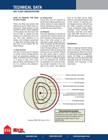
TECHNICAL DATAARC FLASH CONSIDERATIONS816exmweb.com | 1-800-363-2423 | [email protected] TO REDUCE THE RISK OF ARC FLASHThere are three key factors that determine the Arc Flash event on personnel. These factors are the quantity of fault current available in the system, the time fault until the arc flash is cleared and the distance an individual is from the arc. The main objective is to design and configure equipment in ways that minimize these factors and in turn reduce the Arc Flash Hazard. 1) Fault CurrentThe fault current can be reduced by using current limiting devices such as grounding resistors or fuses. If the fault current is limited to 5 amps or less, then many ground faults self-extinguish and do not continue into phase-tophase faults. 2) Arcing Time Arcing time can be reduced by temporarily setting upstream protective devices to lower setpoints during maintenance periods or by employing zone interlocking. 3) DistanceThe main objective is to be able to minimize the number of times one has to access a control panel during a time when power is still required to keep equipment running. Providing remote operators or plug-ins that can allow operators to change settings or monitor performance without opening the enclosure is one method. Robots are also being used to perform activities that are high risk for Arc Flash, such as racking breakers on a live electrical bus. Another consideration is to have the drawing pocket mounted on the outside of the panel. The distance from an arc flash source within which an unprotected person has a 50% chance of receiving second degree burns is referred to as the \Those conducting flash hazard analyses must consider this boundary, and then must determine what PPE should be worn within the flash protection boundary. RESEARCHThere is ongoing research being done on the topic of Arc Flash by all organizations that are involved in improving electrical safety standards. Arc Flash is a relatively new topic and the standards that presently exist will most likely be reviewed and improved in the near future.Flash protection boundaryLimited approach boundaryLimited spaceRestricted approach boundaryRestricted spaceAny point on an exposed,energized electrical conductoror circuit partProhibited spaceProhinited approach boundarySource: NFPA 70E, Fig. A-1-2.4Flash protection boundary:An approach limit at a distance fromexposed live parts within which a personcould receive a second degree burn if an electric arc flash were to occur(NFPA 70E).
